Suspension
CV Joints - General Information, Removal, Installation, and Maintenance
This guide is preserved from Clark's Garage, a foundational 944 resource. View the original →
Tools you'll need
- P229 / 9201 Camshaft Holding Tool
- P238 Harmonic Balancer Holding Tool
- Various Torque Wrench — 200–400 Nm
- Various Torque Wrench — 10–130 Nm
See the full tools list for where to buy each one and budget alternatives.
Torque specifications
Quick reference for the fasteners in this procedure — see the steps below for full context, and verify against your model year.
| Fastener | Size | Torque |
|---|---|---|
| CV joint to flange bolt (cheesehead) | M8 · 8 mm 12-point | 42 Nm (30 ft-lb) |
Credits
Many thanks to Ben Davis for taking the time document this procedure with pictures.
General Information
CV Joint maintenance is an important part of any routine maintenance checks. However, it is often neglected until the CV Joints start to give problems. CV Joints normally let you know when they start to go bad. You’ll hear a clicking sound coming from the rear of the car that can normally be pinpointed to one side of the car. The clicking may be heard during normal driving or in a turn on the outside rear axle.
Quite often a clicking CV Joint can be repaired by simply removing the axle, cleaning the CV Joint, and repacking. Over time, the grease in the CV Joint tends to disappear, even on CV Joints with boots that are in perfect condition. Don’t ask me where it goes, I don’t know.
If a CV Joint is damaged and needs to be repaired, there are several options. Individual CV Joints kits are available from Porsche. I don’t know off hand, if they are available from aftermarket suppliers. You can also purchase complete new or rebuilt axles. Or, if just the boot is bad, you can purchase a boot kit. The part numbers for all these are included below.
| PARTS | |||
| Part Number | Description | Application | Quantity |
| 944 331 901 00 | CV Joint Kit | 1977-1988 924/S/T 1983-1991 944/S/S2 1986 944T | 4 |
| 951 332 901 00 | CV Joint Kit | 1987-1991 944T | 4 |
| 944 331 903 00 | Boot Kit | 1977-1988 924/S/T 1983-1991 944/S/S2 1986 944T | 4 |
| 951 332 901 00 | Boot Kit | 1987-1991 944T | 4 |
| 477 501 103 | Axle - Manual Transmission | 1977-1985.5 924/T, 944 | 2 |
| 477 501 101A | Axle - Left Auto Transmission | 1977-1985.5 924, 944 | 1 |
| 477 501 102A | Axle - Right Auto Transmission | 1977-1985.5 924, 944 | 1 |
| 944 332 038 01 | 1985.5-1991 924S, 944/S/S2 1986 944T | Axle - Manual Transmission | 2 |
| 951 332 038 02 | 1987-1991 944T | Axle | 2 |
| 944 332 038 02 | 1985.5-1991 924S, 944 | Axle - Left Auto Transmission | 1 |
| 944 332 038 03 | 1985.5-1991 924S, 944 | Axle - Right Auto Transmission | 1 |
Tools
-
8mm - 12 point internal tool
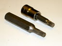
NOTE
The 8mm - 12 point tool is available at most major auto parts stores and is made by Lisle. Sometimes you’ll find it as part of a set of three 12 point tools (8mm, 10mm, 12mm) as they are used in a number of GM applications. However, if the store has the set of three, they should also be able to get them individually as well. Bear in mind before you pass on the set of three that the all three sizes are used in various applications on the 944. The 8mm tool is also used on the pressure plate to flywheel bolts. The 10mm is used on the Camshaft sprocket bolt. And, the 12mm is used on the flywheel to crankshaft bolts. These tools are also known as “cheesehead” tools and if you get them from Snap-On, it’s a “triple square” tool. The Lisle tools have the 12 point on one end and a hex head on the other end, so they have to be inserted into a socket to be used. They are also relatively inexpensive (around $8 USD each). The Snap-On tool is significantly more expensive (around $25 USD) . However, the quality is better, they have a lifetime warranty, and the 12 point is mounted in a socket.
-
Metric socket set
-
Channel lock pliers
-
External snap ring pliers
-
Paint marker or bright colored nail polish
-
Punch
-
Hammer
-
Solvent (Mineral Spirits or Brake Cleaner)
-
CV Joint grease (Moly based)
-
Rags
Procedure
-
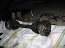
Place the rear of the vehicle on jack stands and place blocks in front of and behind the front tires.
-
Using the paint marker or nail polish, mark the orientation of the drive axles before removal.
NOTE (Tech Tip provided by Ben Davis)
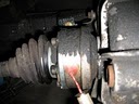
If you are re-greasing your CV joints, odds are a lot of grease has leaked out and is probably caked to the outside of the CV joint, the axle, and the boot. It is probably also caked deeply into the bolts which make for difficult bolt removal, and probable stripping of your bolt or your cheese-head bit. A quick pass with a power-washer can simplify matters drastically, or getting the gunk out of the bolts with a brush and some solvent. It’s well worth the few extra minutes.
-
Using the 8mm 12 point internal tool, remove the cheesehead bolts holding the axles to the transaxle and to the wheel hub.
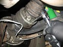
NOTE
It will be necessary to hold the wheel while loosening the CV Joint bolts. If the car is low enough, you may place a block underneath the wheel. Otherwise you’ll have to hold the wheel yourself, or have an assistant hold the wheel, or lock the wheel by using the parking brake or placing the transaxle in gear while loosening the bolts.
-
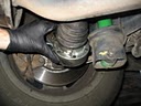
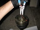
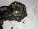
When all bolts are removed, carefully lower the drive axle from the vehicle and place on a clean working surface.
-
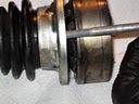
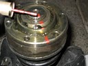
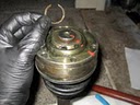
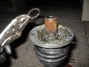
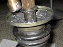
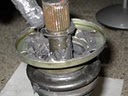
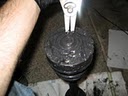
Use a punch and hammer to tap gently around the outside edge of the CV Joint to separate the collar from the CV Joint housing.
-
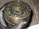
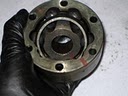
Wipe al the grease away from the end of the CV Joint. Using a paint marker or nail polish, mark the end of the CV Joint from the center shaft across all components to the outside edge.
-
Using the external snap ring pliers, remove the circlip at the end of the drive axle shaft.
-
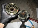
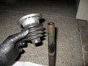
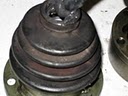
Push the shaft out of the end of the CV Joint. If the shaft is difficult to push out, tap on the end of the shaft with a flat tip punch and hammer to loosen it.
-
Remove the concave washer from the axle shaft. It may be necessary to use the Channel Lock pliers to remove it from the shaft.
-
Slide the boot off the end of the drive axle shaft.
-
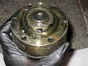
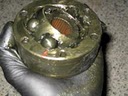
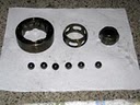
Turn the inner race until the balls align with the grooves in the outer race. Then tilt the inner race to separate the inner race from the outer race.
-
Push the ball bearings out of the inner race.
NOTE
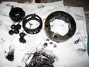
When disassembling the CV Joints, be sure to keep the parts from each CV Joint together. Don’t mix them with the parts from other CV Joints.
-
Clean all of the CV Joints parts (races, splines, and ball bearings) with solvent and inspect for damage. If any of the parts show signs of excess wear or cracking, the entire CV Joint must be replaced.
-
Apply a small amount of grease to the ball bearing grooves on the inner race. Using your fingers, press the ball bearings back into the inner race until they snap into place.
-
Assemble the inner and outer races by aligning the ball bearings with the grooves in the inner race and tilt the inner race into the outer race.
Tech Tip provided by Ben Davis
If you are having difficulty inserting the inner race into the outer race with the ball bearings intact, you may find it easier with this alternative method: Remove all the ball bearings, then insert the inner race into the outer race, and tilt the inner race while installed to insert the ball bearings one at a time. After the last ball bearing has been inserted, the inner race will already be in place.
-
Inspect the CV Joint boot for rips, tears, or wear and replace if necessary. Apply a small amount of grease or silicon spray to the axle shaft opening in the boot. Slide the boot onto the axle. Place a small amount of grease on the inside of the boot.
-
Slide the concave washer onto the splines of the axle. Use a hammer and deep socket to tap the washer down all the way to the bottom of the splines.
-
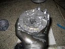
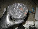
Thoroughly repack the CV Joint with grease.
-
Apply a small amount of grease to the axle splines.
-
Check the align marks on the end of the axle shaft and on the CV Joint inner and outer races. Slide the CV Joint onto the axle making sure all of the marks are aligned.
-
Install the circlip on the end of the axle shaft to lock the CV Joint into place.
-
Tap the CV Joint boot collar into place on the CV Joint.
-
Reinstall the axle into the vehicle.
-
If any of the heads on the cheesehead bolts were damaged during removal, replace with new hardware. Install all of the bolts on both ends of the axle finger tight first.
-
Using the 8mm 12 point internal tool and a torque wrench, torque the cheesehead bolt to 30 ft-lbs (42 Nm). It will be necessary to somehow lock the rear wheel while torquing the bolts.
-
Remove the vehicle from the jack stands.
-
Test drive the vehicle, slowly at first, gradually increasing speed while listening for unusual noises.